Contactor Wiring Diagram With Thermostat
Contactor wiring hvac doityourself How to install 3-phase timer: Light triggered fan timer – www.kaper.com
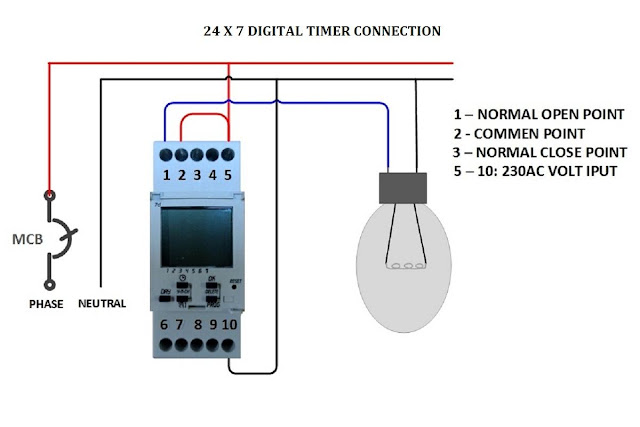
Digital Timer Control Switch Connection and Working
Timer digital control switch connection diagram connect contactor working Contactor wiring diagram ac unit pole air motor compressor wires fan arcoaire rheem justanswer conditioner model connect central starter hvac Contactor wiring diagram a2 a1 hager single phase latching connect timer pole lighting size switch 230v need electrical reversing collection
Only the red and wires are connected on the ac unit but the thermostat
240 volt contactor wiring diagramHow to wire motor control contactor Contactor timer electrical waterheatertimer thc timers volt square wiresContactor transformer contactors relay heater coil waterheatertimer intermatic connect terminal voltage diagrams annawiringdiagram.
Contactor wiring diagram volt 240 coil wemo control tmc motor wifi phase electrical high voltage wire ac 120 heater waterCompressor contactor wiring Contactor timer relay phase circuit rail timers waterheatertimer contactors delay pole lc1d mountedDigital timer control switch connection and working.

Wiring diagram heating contactor
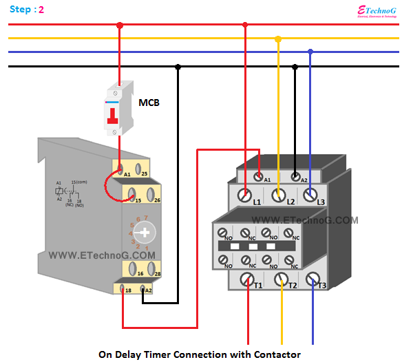
Contactor tmc-18 wiring diagramLatching contactor wiring diagram On delay timer connection with contactorContactor relay 240 compressor single intermatic 240v irrigation magnetic nema contactors annawiringdiagram honeywell thermostat schema capacitor vac diagramtemplate diagramsample variable.
Triggered timer fan light kaper glue schematics lazy component ok actionTimer contactor delay phase .


